d7f77a72a9772b495b16bdba687bbf5a64f30c94

facebook
instagram
youtube

elide@elide.it

590f35719e18241313cdd03f87ba0de0f711622a

Elide Sulsenti © 2021


facebook
youtube
img_5243.jpeg

DIY MOTORISED INSTRUMENTS

Designing and building a new circuit to play Lisa Streich's Pietà

screenshot 2025-05-31 alle 16.58.14

How it started…

This project I share here documents the reconstruction of the motorized system for Pietà, a piece by Swedish composer Lisa Streich for motorised cello and motorised instruments installation. This work originated from a very concrete situation: the original system, created at IRCAM when the piece was first conceived, was characterized by a particular delicacy, meaning the unpredictable behaviour of the system, but also his sensibility to every movement or sound of the performer.


My re-design was not just technical, but relational. I worked in dialogue with the composer, carefully studied existing versions, and designed a new Arduino-based circuit capable of automating the motor movements through a synchronized timeline. The result is a system that is more stable, reproducible, and with a more legible script, allowing the performer to interact with the setup more naturally guided by a click track and able to focus more deeply on interpretative expression.


This reconstruction stands, for me, as a clear example of how taking care of technical objects is an essential part of the performative act. Caring for a fragile system, making it transmissible, turning it into something truly usable and understandable, is a gesture that speaks as much to the technical dimension as it does to the ethics of making music today.

tw-12

How to build a circuit for performing PIETÀ by Lisa Streich

Materials List

To build the motorized circuit, you will need:


Electronic Components

  • 11 × DC gear motors (6V)
  • 11 × copper prototyping boards (breadboards or stripboards)
  • 11 × N-channel MOSFETs (e.g. IRLZ44N or similar logic-level)
  • 11 × 1kΩ resistors
  • 11 × 220 Ω resistors
  • 11 × diodes (e.g. 1N4007, to protect the circuit from voltage spikes)
  • 11 × male XLR connectors
  • 11 × female XLR connectors
  • 11 × pin headers / pinout connectors 
  • Wire cables for Arduino and circuit connections (various lengths)
  • 2 ready-made bus-bars / 2 screw terminal blocks (to be prepared)


Power and Connectivity

  • Power supply: 9V, 5A 
  • Power jack connector: compatible with your power supply (in my case 2.1 mm x 5.5 mm)
  • Approx. 20 meters of positive and negative electrical cable (preferably color-coded)
  • 1 × flame-retardant enclosure (box to house the central circuit safely)


Control Interface

  • 2 × Arduino Uno boards (or equivalents)

Step 1 – Preparing the Enclosure

To start building the circuit, the first step is preparing the enclosure.

I used a standard cable management box, like the ones typically used in offices to hide wiring.

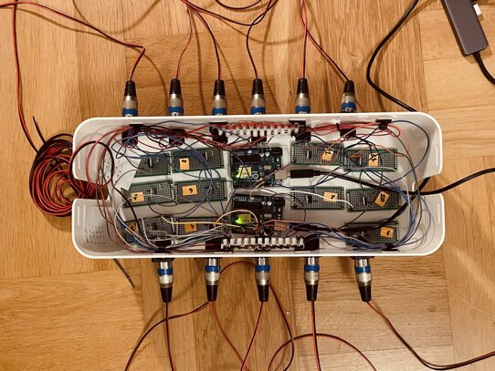
I drilled 11 holes in the front panel to fit the 11 male XLR connectors that will serve as the outputs of the motor control system.

Each hole should match the diameter and positioning of the selected XLR connectors to ensure a stable fit.


After this, I also drilled an additional hole on the side or back of the box to house the DC power input — in my case, a 2.1 x 3.5 mm jack suitable for the 9V 5A power supply used for the system.


Step 2 – Building the Control Circuit Boards

Once the box and XLR holes are ready, the next step is to assemble the individual circuits for each motor.

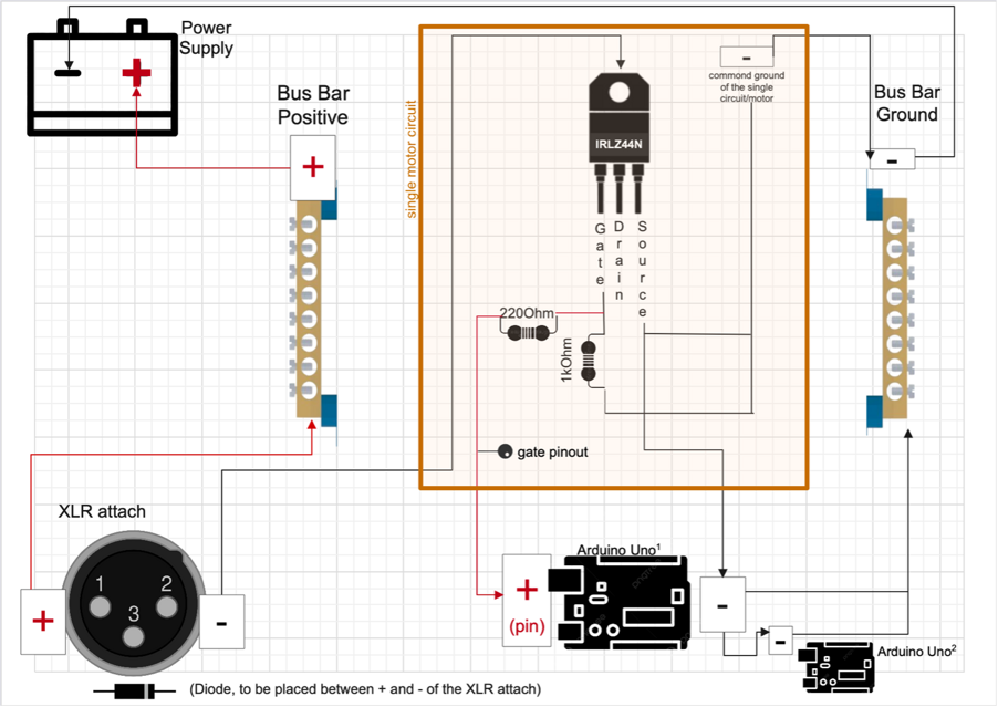
Each of the 11 motors is controlled by a dedicated small copper board, where the following components are soldered:

  • 1 x MOSFET IRLZ44N (or similar logic-level N-channel MOSFET)
  • 1 x 220Ω resistor
  • 1 x 1kΩ pull-down resistor
  • Wires for power (positive and negative) and signal
  • A pin connector to link the signal to the Arduino

(The very important flyback diode it’s soldered directly on the XLR attach)


You will find a photo showing the wiring diagram and assembly example in the following section.

Here there is a video of the circuit assembly:

…and here of how to solder the circuit (you can judge my soldering skills :) )

Step 3 – Wiring the XLR Inputs and Adding Diode Protection

Each XLR connector on the front panel of the box requires a protection diode soldered between Pin 1 (signal) and Pin 2 (ground).

  • The cathode of the diode (marked by a white band) should be connected to Pin 1 (positive/signal).
  • The anode (unmarked side) should be connected to Pin 2 (ground/negative).

This diode setup helps protect the control circuit from reverse polarity or unexpected voltage spikes at the input.

A wiring diagram illustrating this setup will follow this section.

Once the diodes are installed, solder the connections, fasten the XLRs in place, and proceed with internal wiring toward the motor controller boards.


Each XLR connector is then connected to its corresponding MOSFET output:

The negative lead (pin 2 of the XLR, where the cathode of the diode is also connected) must be wired to the drain of the assigned MOSFET. This ensures that the negative signal passes through the MOSFET to complete the switching circuit.


senza titolo

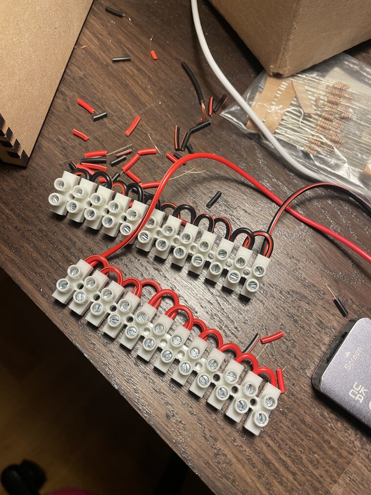
Step 4: Preparing the Screw Terminal Blocks (skip this step if you have ready-made bus bars)

To turn each Screw Terminal Block into a continuous rail (i.e., making all its terminals electrically connected), you need to bridge the terminals manually. Start by cutting a piece of insulated wire into several short segments, each about 2 centimeters long. Strip approximately 5 millimeters of insulation from both ends of each segment. Then, insert each wire segment across two adjacent terminals: connect terminal 1 to terminal 2, terminal 2 to terminal 3, and so on, until all terminals in the block are interconnected. Tighten the screws to secure each wire segment in place. When done, each terminal in the block will be electrically linked to the next, forming a shared positive or ground rail, depending on its intended function in the circuit.


img_5098.jpeg

Step 5: Connecting Screw terminal blocks / bus bars to the power supply

Now, take the power jack connector, compatible with your power supply. Connect the positive-bus bar with the positive of the connector (usually the pin in the center), the negative-bus bar with the negative.


Step 6: Final Circuit Integration

At this stage, all components of the circuit are connected. The positive and negative bus bars are directly powered through the jack input mounted on the enclosure. From here:

  • The common ground of each motor circuit is connected to the ground bus bar.
  • Both Arduino Uno boards have their GND pins connected to the ground bus bar as well, and an additional ground wire links the GND of one Arduino to the GND of the other, ensuring a stable shared reference.
  • The positive output (Pin 1) of each XLR connector is connected with a wire cable to the positive bus bar to supply power to the motors.
  • The negative return line from each motor-circuit (via the MOSFET drain) is routed back to the XLR Pin 2, completing the circuit through the controlled ground path.

This configuration ensures that power is distributed correctly across all components, with a unified ground reference and safe current routing via the MOSFET-controlled motor lines.

Step 7: Assembling the Motors and Cabling System

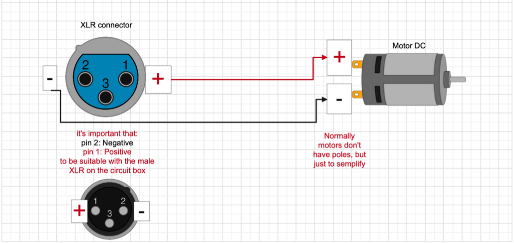
For each of the 11 DC motors, I prepared a dedicated cable of approximately 1.5 meters in length, consisting of a positive and a negative wire. Each wire was soldered directly to one of the two motor terminals: the positive wire to one terminal, and the negative wire to the other. I then connected the wires to an XLR female connector, where the positive wire was soldered to Pin 1, and the negative wire to Pin 2, following the standard configuration used in the control box.


senza titolo1

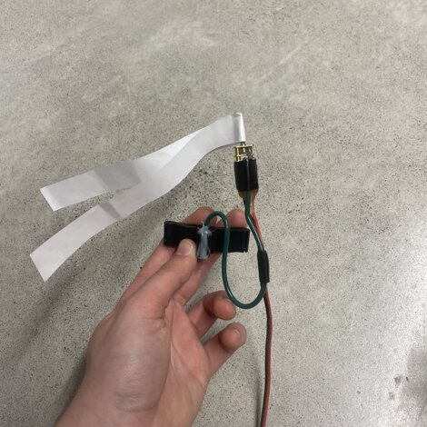
Once each motor was connected to its XLR cable, I moved on to building custom holders for instrument mounting. These supports were tailored to each use case:

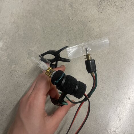
  • For the motorized solo cello, I used a clip-on microphone mount (placed on the tailpiece). Two motors were attached here:
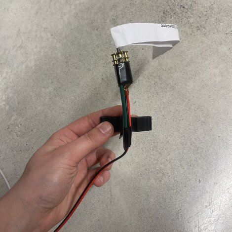
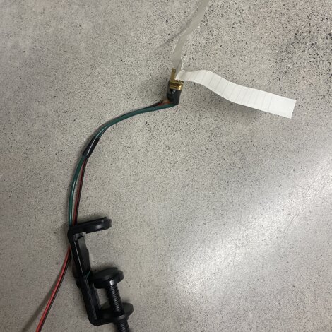
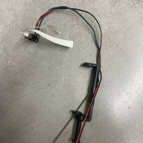
    • One motor was fitted with a plastic strip (cut from a plastic book cover, about 7–8 cm long) that rubbed against the soundboard. The motor was positioned near the cello’s soundboard using a shaped gardening wire support.
    • The other motor rubbed against the tailpiece itself, using a double-layered plastic blade (two plastic strips nested together and fixed with hot glue).
      Both strips were glued to the motor shafts using hot glue
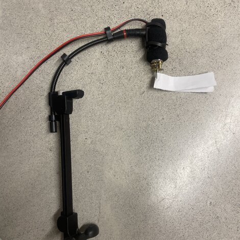
  • third motor was mounted to rub against the soundboard with a paper strip. This was held in place using another microphone holder, to which I attached a steel gardening wire structure, bent to reach the correct surface area. The paper strip was glued perpendicularly to the motor shaft.
  • The fourth motor, positioned to pluck the strings behind the bridge, was also mounted using a DPA mic clipand a support made from gardening wire. The wire was shaped to elevate the motor and position the paper strip(this time cut to the full length of an A3 sheet) above the string set. Again, the strip was affixed securely to the motor shaft with hot glue.
senza titolo1img_7636.jpegimg_7642.jpeg

Additional Instrument Motor Mounts

Following the setup of the motors for the solo motorized cello, I proceeded with the installation of the motors on the remaining instruments involved in the installation. Each setup was adapted to the physical characteristics of the instrument and the acoustic behaviour of the motor activation.

  • Guitar:
    I used a mounting system similar to the one employed for the cello motor rubbing the soundboard with paper. A clip-on mic holder was attached to the body of the guitar. A slightly longer gardening wire was bent and fixed to the holder, ensuring it reached the appropriate surface. I used a thinner type of paper strip than that used on the cello, as the guitar strings and soundboard are more delicate and responsive to lighter materials.
    For the preparation of the guitar, I followed the initial instructions from the composer by attaching three helical paperclips to the strings. However, the specific preparation may vary, and it's important to consult the composer directly for confirmation and updates on the required setup.
  • Violin:
    clip-on microphone holder was adapted to fit the smaller dimensions of the violin. The system was scaled appropriately, using shorter support wire and lighter motor settings, maintaining ergonomic and sonic compatibility with the instrument’s structure.
  • Second Cello:
    For this instrument, I reused the same motor mount strategy employed for the fourth motor of the solo motorized cello — the one designed to pluck the strings behind the bridge. A mic clip was combined with a gardening wire armature to position the motor securely, and a long A3 paper strip was glued to the motor shaft for plucking action.
  • Grand Piano:
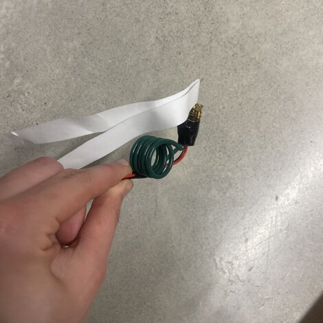
    For this instrument, I designed a modular and adaptable rail system using a curtain rod as a structural base. This rod can be installed inside any grand piano, regardless of brand or size.
    Onto the curtain rod, I coiled spirals made from gardening wire, one for each of the four motors. These spiral mounts function like adjustable springs: they can be extended or compressed depending on the size of the piano's interior. Once in place, they are secured with duct tape or repositionable adhesive strips.
    Each motor was fitted with a long A3 paper strip, which is positioned to make contact with the piano strings inside the instrument.
img_7639.jpegimg_7644.jpegimg_7640.jpegimg_7643.jpeg

Step 8: Downloading and installing the scripts/projects

Download THIS FOLDER


It contains a MaxMSP project (adapted from a previous project by Alessandro Perini, to perform his piece “Epicentro” for piano, 10 vibration motors and two contact microphones), including Port D and Port E patches; a Reaper Project, with the timeline and each motor line; the 2 Arduino scripts for Port D and Port E. 


To install the scripts into arduino, first install on your Computer ArduinoIDE. Then write both scripts, port D in one Arduino, Port E in the other.

Step 9: Connecting motors-circuits with Arduinos

Last step to make the circuit work it’s to connect each circuit to Arduino.

Take 11 male-female circuit connections for Arduino, the male side goes to the pin header on the circuit of the single motor, the female on one PWM pin of Arduino.

I connected as following. The second number corresponds to the corresponding MIDI channel in the Reaper Project


screenshot 2025-06-02 alle 22.53.51

I suggest to write the numbers on each board and under each XLR attach, and the name of the corresponding Port on each arduino.

Step 10: Play with the circuit

Once you have everything done:


-       Connect each motor to the XLR attach

-       Connect to the computer first Arduino Port D, then Arduino Port E (in this order)

-       Connect the power jack to the power supply

-       Open the Max sitoPatches, press D on the patch of PortD, E on the patch of PortE 

-       Open Reaper Project, make sure that communicates via MIDI with MaxMSP

-       Plug your headphones for Click track

-       Now play with it  …if it doesn’t work, you can contact me Here :)

screenshot 2025-05-31 alle 16.58.14